Cascading SCARA Bot
Chess Bot
Given the broad nature of the project, an engineering design process was used to define the development of the project over the course term. The first stage of this process entailed planning a needs analysis on the problem, where the scope of the robot was defined. During a needs analysis, the constraints, functional requirements, and non-functional requirements determine the baseline of what the robot should/must accomplish and serve as the basis for evaluating the successfulness of the design.
For our project the requirements were defined as follows:
-
Functional Requirements:
- The robot successfully plays chess without any human intervention
- The robot will move in three cartesian axes: the x, y, and z
- The robot should be able to perform chess movements without any human intervention
- The design should be easy to operate and have a fast startup and setup time
- The design should be safe to use and not present any potential hazards during operations
- The robot must be cost effective and the total cost should be under $200
- The robot must be easy to transport and thus weigh under 10kg in its fully assembled state
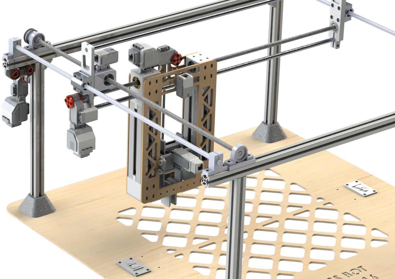 The next process that followed was conceptual design where we ideated on potential designs that would address the requirements. We had several designs but ultimately settled on one that we liked the most through a weighted decision matrix. Ultimately, the design drew inspiration from the layout of core-XY or other convention layout 3D-Printer. However instead of a rigid vertical Z-axis, we went with a rigid XY setup and compliant Z-Axis since most of the distance would be covered along the X and Y.
Z-Drive Axis
The z-axis controls the vertical degrees of freedom of the end effector through a carriage element. The z-axis is a belt driven mechanism where 20T GT2 pulley is locked onto the large EV3 motor controlled the driving motion and passed through an idler pulley for fluid motion. To address any slippage in the belt of the part, the belts are separately joined on the carriage plate to provide a passive tensioning system for the belts. In the first iteration of the design, the pulley was offset which caused the carriage to slant and needed a redesign. In the latest iteration, the pulley is centred such that the forces on the carriage can propel the carriage component fluidly without any drag. Another issue faced with the Z gantry is slanting that occurred in one of the designs of the part, where the load of the carriage was much heavier on one side than the other despite having a tolerance of less than 0.5mm enclosed between the plate and the bearings. This meant that the issue did not pertain a lack of precision in tolerancing but rather a different solution needed to be implemented. One observation was that the plate would no longer be aligned, in other words, the direction of the bearing would no longer be perpendicular to the plate. So, a way to simply inhibit the displacement of the plate was to add another bearing to that would constrain its degrees of freedom (DoF) to be strictly parallel to the plate.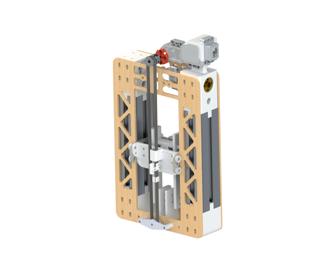
End Effector (Redesign)
The original end effector design used a linkage based system guided by a 1/4" bolt to lock additional DoF. There were multiple iterations made for this end effector but when the part was trialed in assembly level, we found that the motor did not have sufficient torque to power the part. So we needed to redesign the end effector in a constrained time frame with consideration that it must be drivable by the EV3 motors and that it must be resetable (to a default positioning) with high repeatability.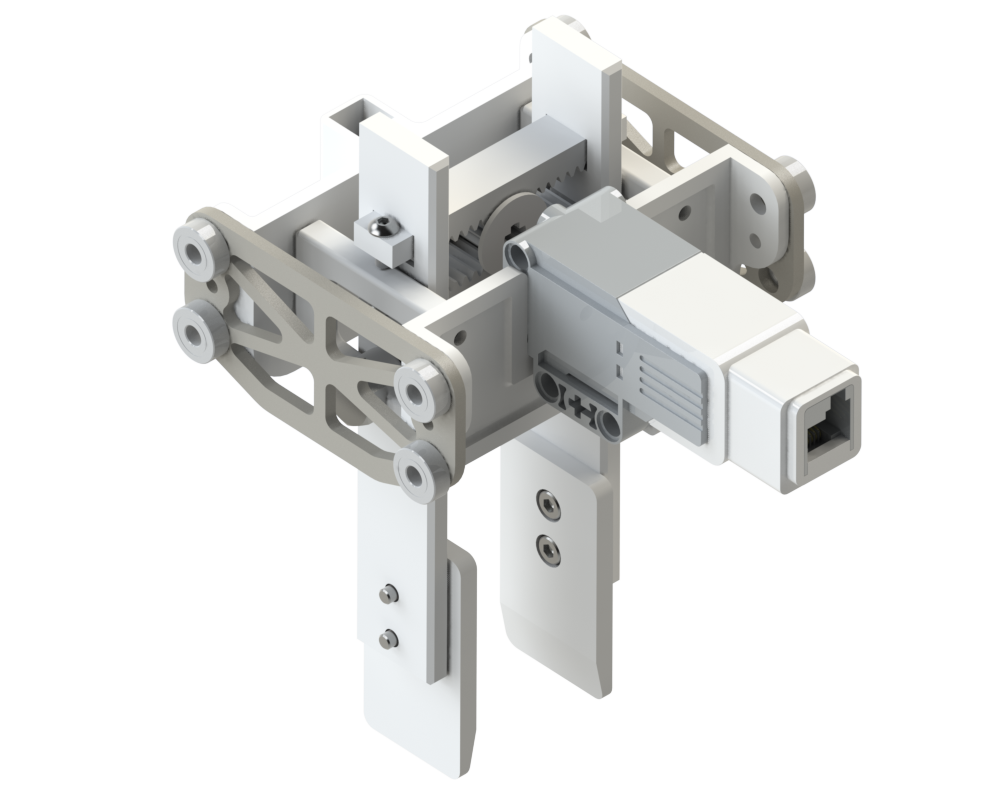
Y-Drive Axis
The Y-Axis mechanism of the chess robot is designed to move the Z-gantry laterally. It features a directly driven motor without any reduction, contrasting with the X-Axis, which bears a larger portion of the gantry's load. This design choice for the Y-Axis enhances the robot's lateral speed, although the motor's power limitations result in a perception of slowness even at full power. Despite its simplicity, the Y-Axis mechanism effectively fulfills its role and facilitates the integration of software, making it a straightforward yet efficient component of the robot's overall design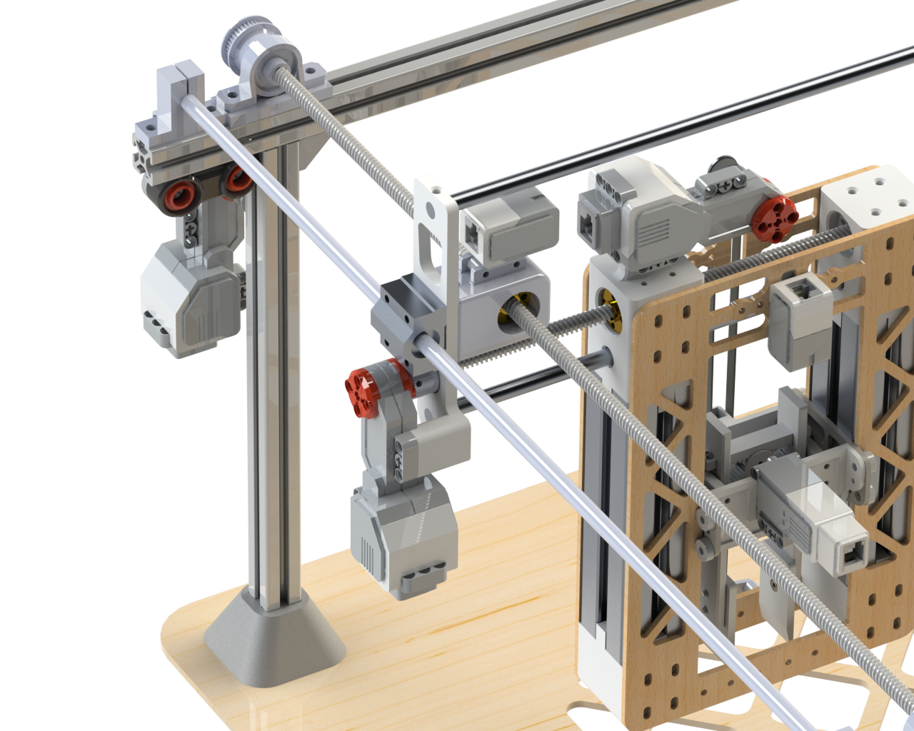
Whack-It! - ME100 Toy Design Project
As part of the first year mechanical engineering course in Waterloo, we were tasked with designing toys as group for Spin Master while documenting our entire iterative design process. Attached below is the report documenting the progress of our toy design and how we were able to reach our end design.
Certified Solidworks Professional in Mechanical Design
Handular
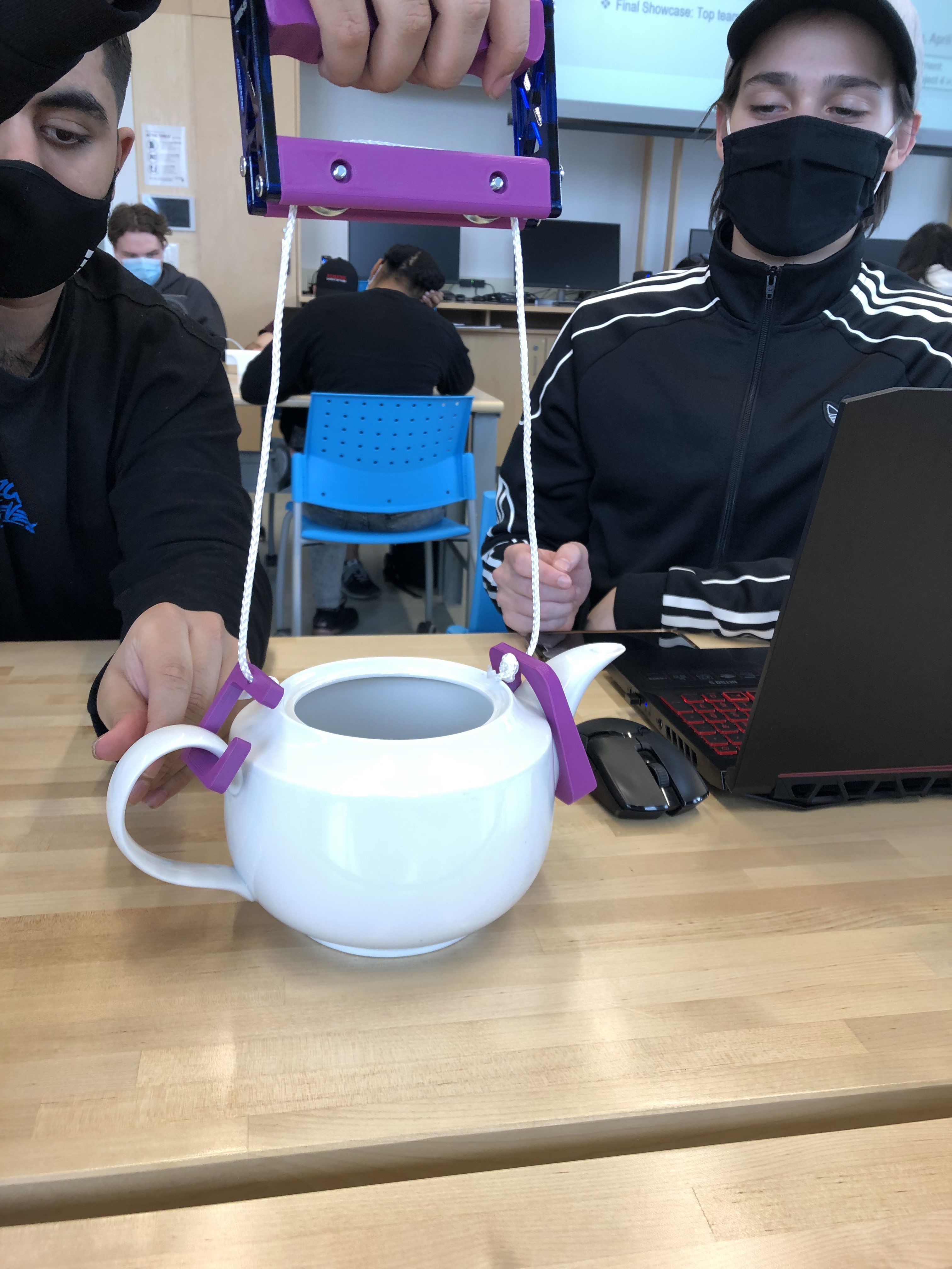
Handular is an assistive device designed to help enable our client to perform daily tasks and was top 5 among 200 other project submissions. Our client, 42 years old, is diagnosed with Ehlers-Danlos syndrome, a rare disorder that affects the connective tissues throughout the body—specifically the joints [1]. The client experiences daily struggle with the syndromes of the condition, explicitly with the tendency of joints dislocating and experiencing subluxation. Since they struggle with several tasks, the nature of the problem was broad.
Design Process
We were given full control over the project and that vague nature meant we could direct our focus into any of our client's struggles. Our problem statement started as: Devise a mechanism for the client to reduce the strain brought on by daily tasks.
Objective Tree
At this point we did not have a concensus on what problem we wanted to focus on so we created an objective tree. The objective helps use determine how we would would implment certain objectives into our design; subsequently, it narrows your options since you have to reflect on the feasibility or implmentation ofthe design within a limited time frame.
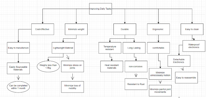
We provided rationale into why implementing ergonomic design, weight-reduction, and durability/maintainability to be our most important objectives.
Narrowing our Problem
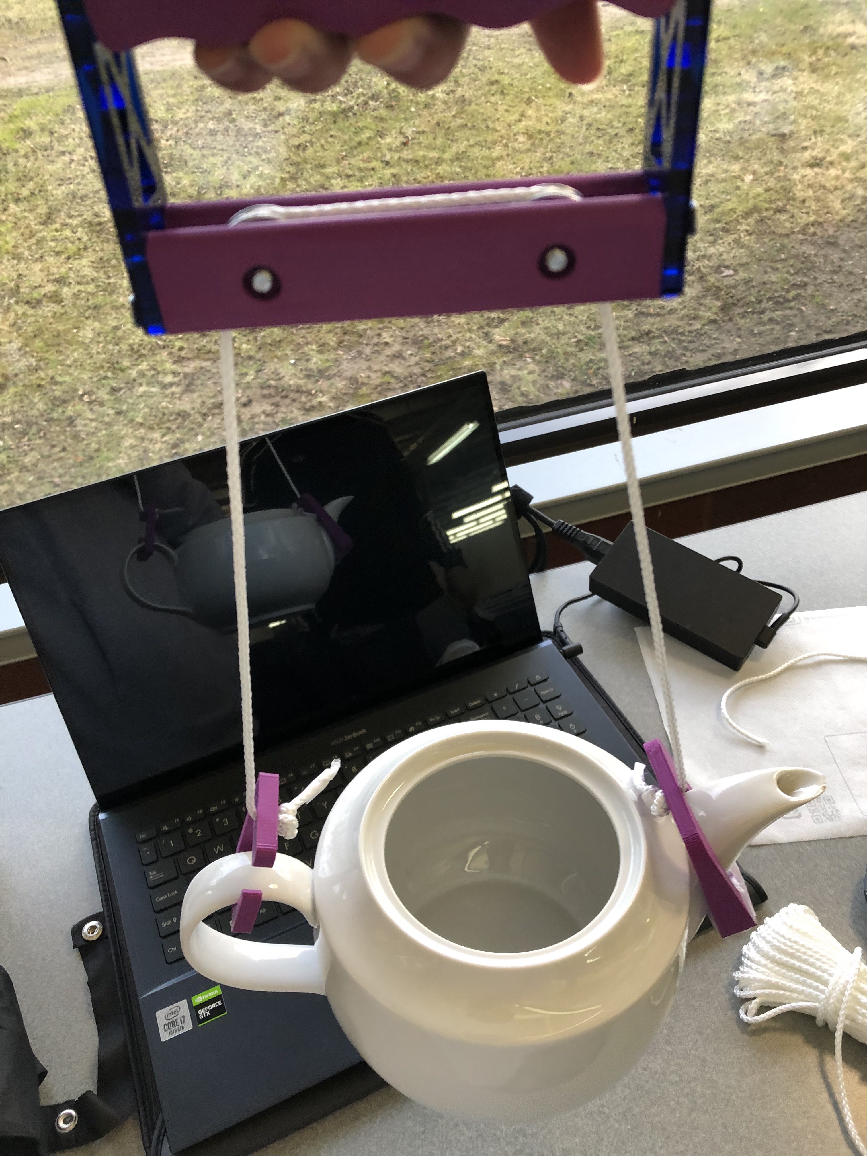
We eventually reached a consensus that we would focus on performing one task well before thinking about other potential implementations. One of the most mechanically approachable problems was his inability to pour liquids out of a teapot due to the strain they experience when rotating the teapot (all the experienced force is put on their finger joints, further aggravating sublaxation).
Here is our refined problem statement: Design an ergonomic and lightweight device that allows our client to pour liquids and minimize the strain on his joints. The client suffers from Ehlers-Danlos Syndrome which can cause trauma to their joints when performing daily tasks. This household device will be easy to use and comfortable for short term use.
Drafting Ideas
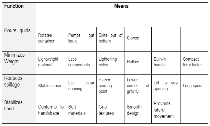
A morphological chart was used to define specific solutions based on our functions and objectives.
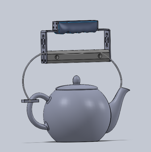
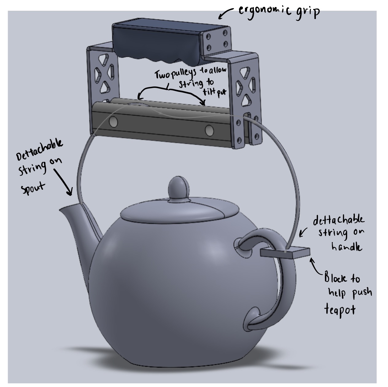
At this point I was also researching ergonomic designs of teapots or kettles. I also wanted to keep in mind that the client was not necessarily looking for a redesign of their daily tasks like another teapot, but rather something that would enable them to perform daily tasks. Keeping in mind this sentiment (which would prove quite important later on), I noticed that most ergonomic teapot designs have their handles on the top because it is much easier to support most of the mass vertically opposed to horizontally. At this point, I started drafting ideas as to how we could create a modular attachment that would allow us stabilize the teapot from above while also allowing the teapot to be rotated.
Design Impracticalities
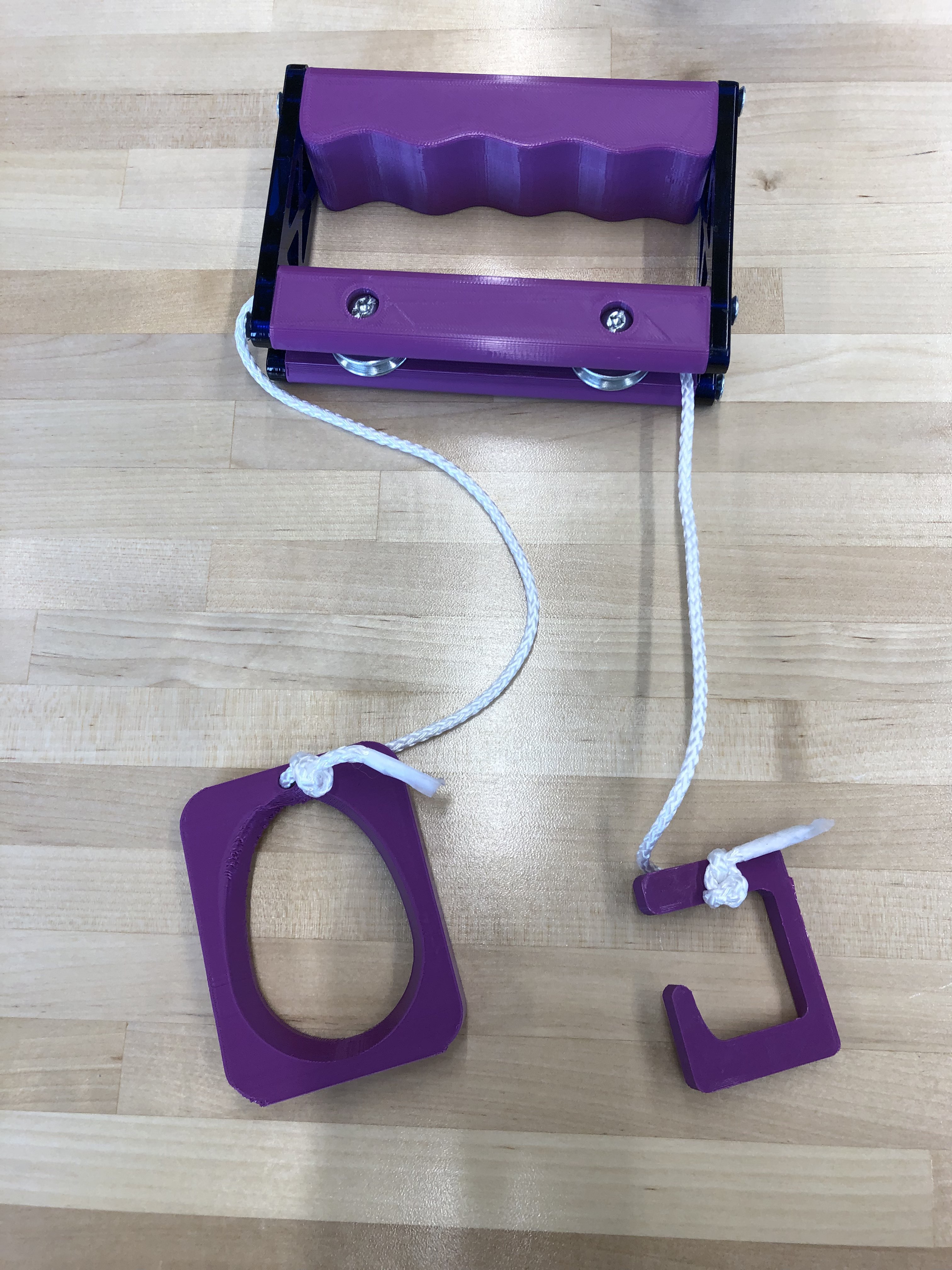
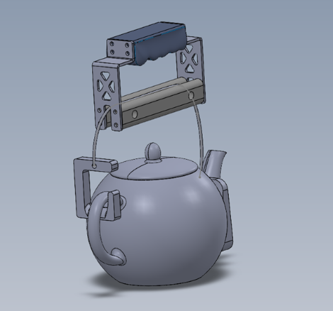
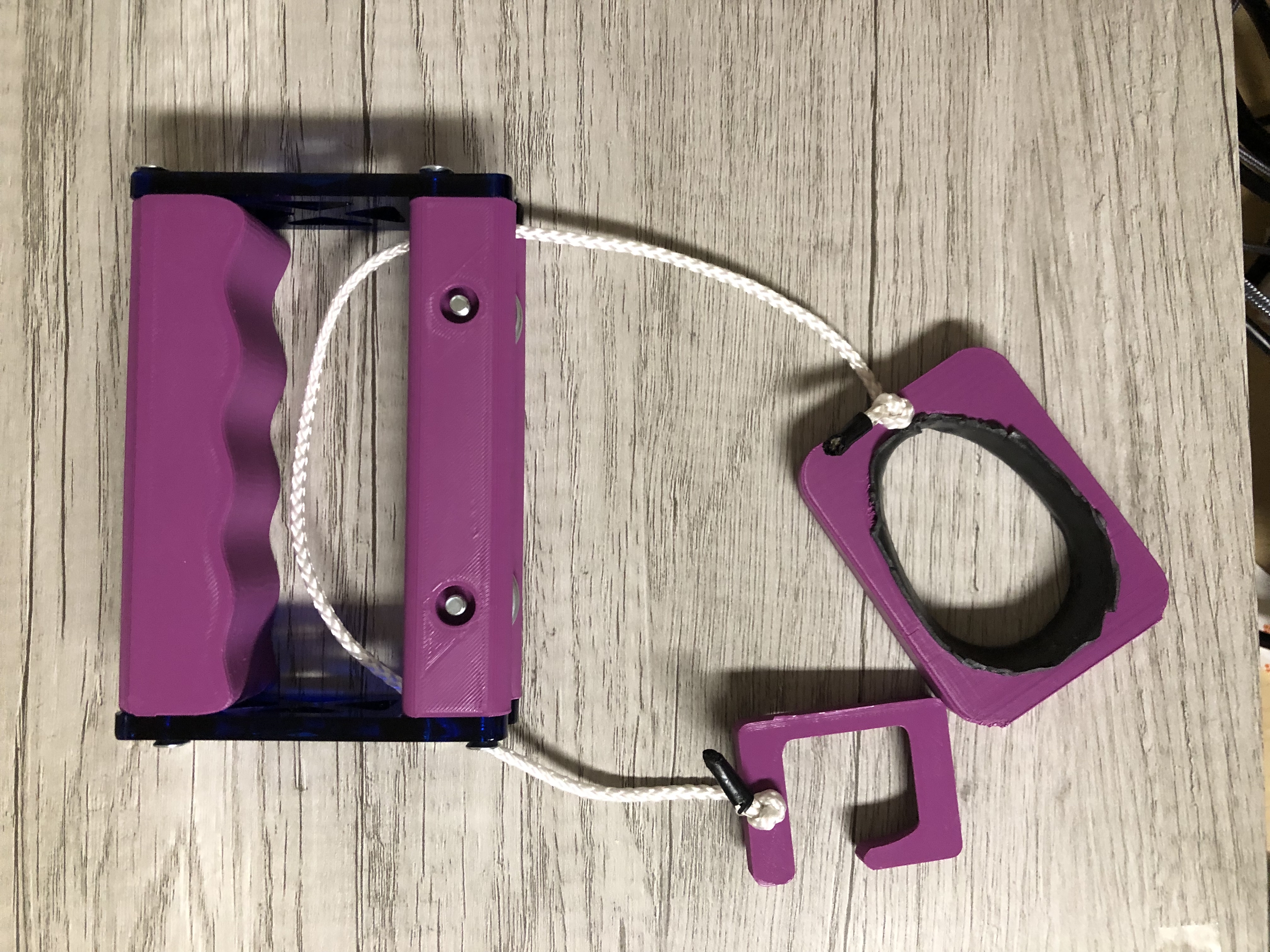
I made CAD mock-ups of how the attachment would look like. However, there were some glaring impracticailities of the design that needed to be addressed. I didn't know exactly how I would design an attachment that would hook onto any teapot from the handle or the spout end (I didn't have any dimensions of the client's teapot). From a designability viewpoint it wasn't ideal because I wouldn't be able to make an exact fit for their teapot. However, this worked out because I wanted to make the device practical which meant it would work for most other teapots. So, I designed a hook that would be big enough for most other teapots using my large kettle handle for reference. As for the spout, every teapot has a different spout design, so I designed a block that should fit in any traditional spout design and drafted the hole to accomodate for smaller designs.
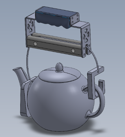
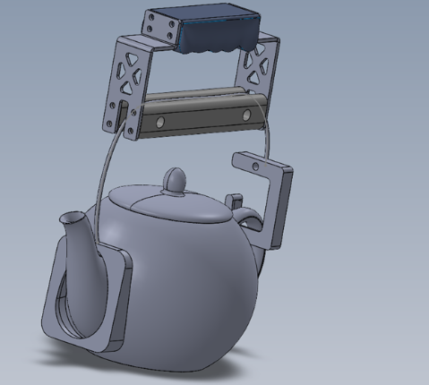
Manufacturability
We needed manufacture a working prototype for our part; however, the complexity of our part required us to use rigid and robust parts which meant cardboard would not work. We decided to get the parts 3D printed and laser cut so some adjustments needed to be made. The handle used something I had just recently learned with Inventor, which was G2 curves that would add a rounded surface over a closed area. But there was no practical way for me to fill the surface with solid material so the G2 surface did not show up when I loaded the stl file for 3D printing. I revised the handle by removing the curve and adding more defined filets to allow for a smooth hold. Consequently, I changed the side guesset because we would not be able to machine the part in metal with our limited timeframe and made it a flat part instead for laser cutting. We believed that have a thick laser cut acrylic sheet would hold up stronger than ABS 3D printing.
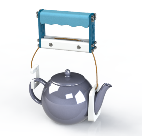
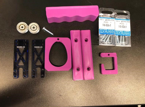
Assembling and Testing
We gathered all our parts and started assembling parts together. In our first test we realized we need adhesion or friction on the spout block so that it would not slip off. We experimented with basic clear tape and fount it worked fairly well until it lost its stickiness, so off that we decided to use mounting tape which would provide adhesion but also a rubbery friction after the adhesion wears off. Aside from that, we shortened the length of the string to prevent additional slippage of the spout block.
Before
After
Modularity
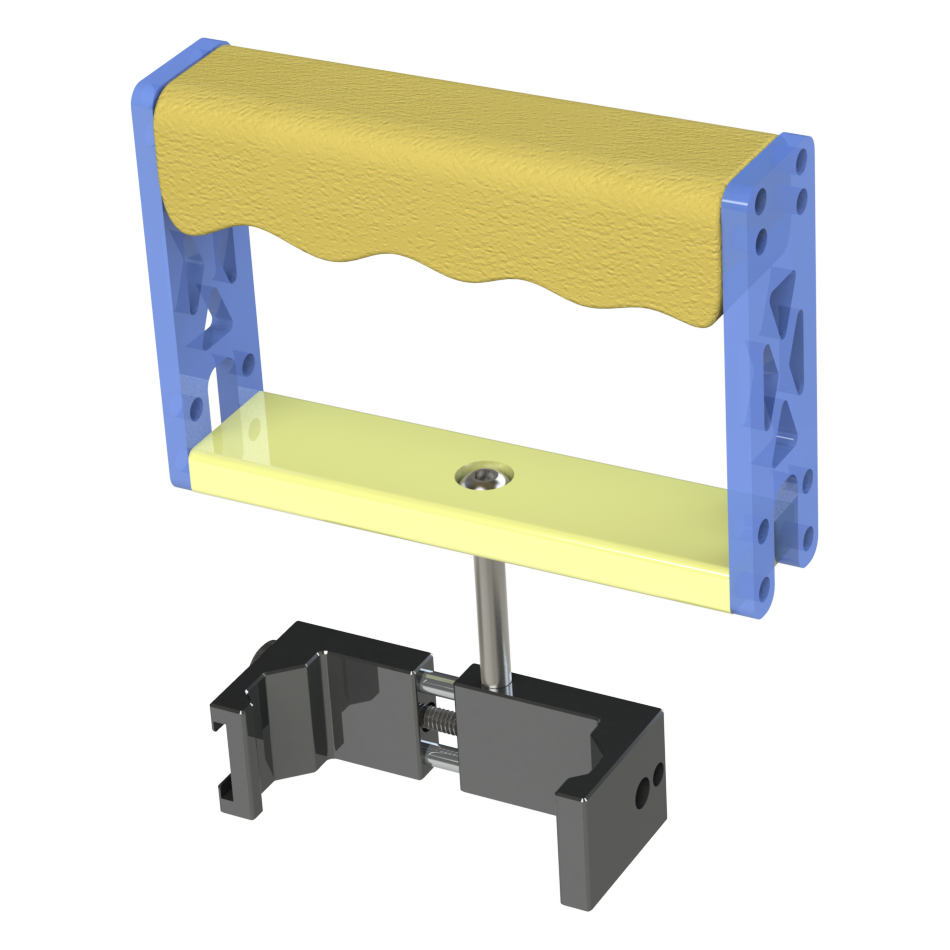
The biggest shortcoming of our design was that it may have been too specific to a niche tasks. So, under our time constraints we wanted to branch out and be ambitious. So I designed a secondary function for the device, that was a phone mount that would help to offset the cramped feeling of holding a phone for too long. This way we added more functionality with the device making it more versatile and helped serve as a basis for our product name, Handular (a modular assistive handle).
Recycling Sorting System
As a preface, a more rigorous and thorough engineering design process was used to create the system. However, I hope to provide a general understanding of how it was create and how it works.
Problem
There is a glaringly overlooked issue with recycling, where the number of items sent to the recycling is not recycled. According to the City of Toronto, 30% of items sent to recycling are not recyclable. As a result, the process of sorting in recycling facilities is much more complicated due whether it be from food or drink residue will affect recyclability.
Problem Statement
In a controlled environment, we can simulate the process of sorting materials and determining where to designate it for recycling. The goal of this project was to design a system which sorts and recycles through all kinds of material based on their classification to prevent improper recycling and reduce the excess waste that enters our landfills and recycling facilities.
Our Approach
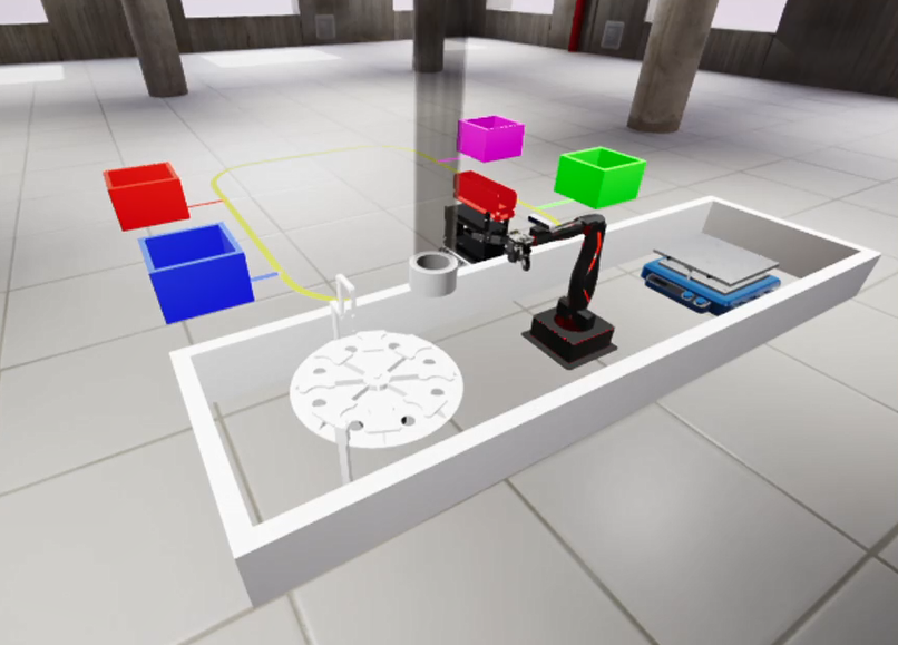
Through using Quanser Lab simulation, an algorithm was designed using Python that would transfer containers from the sorting station to the correct bin the recycling station. This would require us to host the simulation through a Raspberry Pi through which we would also be able to locally connect to simulate the system physically.
Sorting
Sensors were used to determine what type of container was being processed and loaded. For example, using an inductive sensor would tell us if the container is metal can or not. From there, a photoelectric sensor is used to determine whether the material is plastic or paper. Generally, the paper recyclables will have a higher raw reading on the photoelectric sensors than plastic containers which will allow for us to differentiate between the two.
Loading
Knowing which container is on the sorting station will allow us to determine where they should be allocated (to their respective bins). The Q-Arm loads a maximum of three containers given that they are all in the same category of recyclables (and stops loading once a different bin target is introduced).
Transporting
The Q-Bot (the roomba) is programmed to follow the yellow path using a basic algorithm that implements infrared sensors. There are two infrared sensors on each end of the Q-Bot wheel and moves straight when the yellow line is detected. However, if only the right sensor detects the yellow path, the wheel speed of the left side moves faster to correct the angle and vice versa.
Depositing
There were many approaches to differentiate between each bin. For our instance, ultrasonic sensors were used to calibrate distances away from the bin which would allow us to find the corresponding bin.
Source code available upon request. Just send me an email!
Certified Solidworks Associate in Mechanical Design
Sterilization Container
Overview
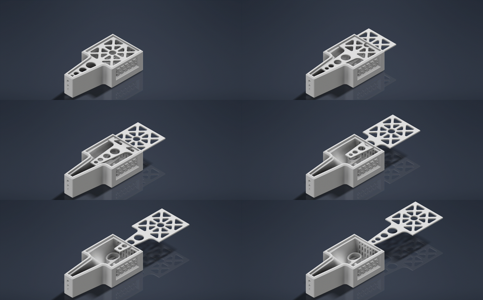
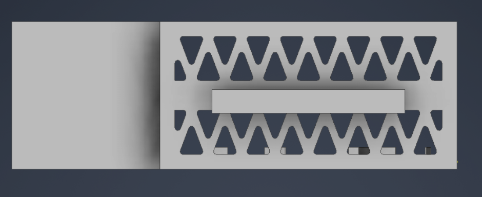
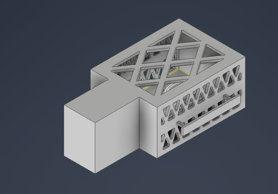
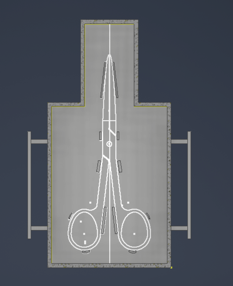
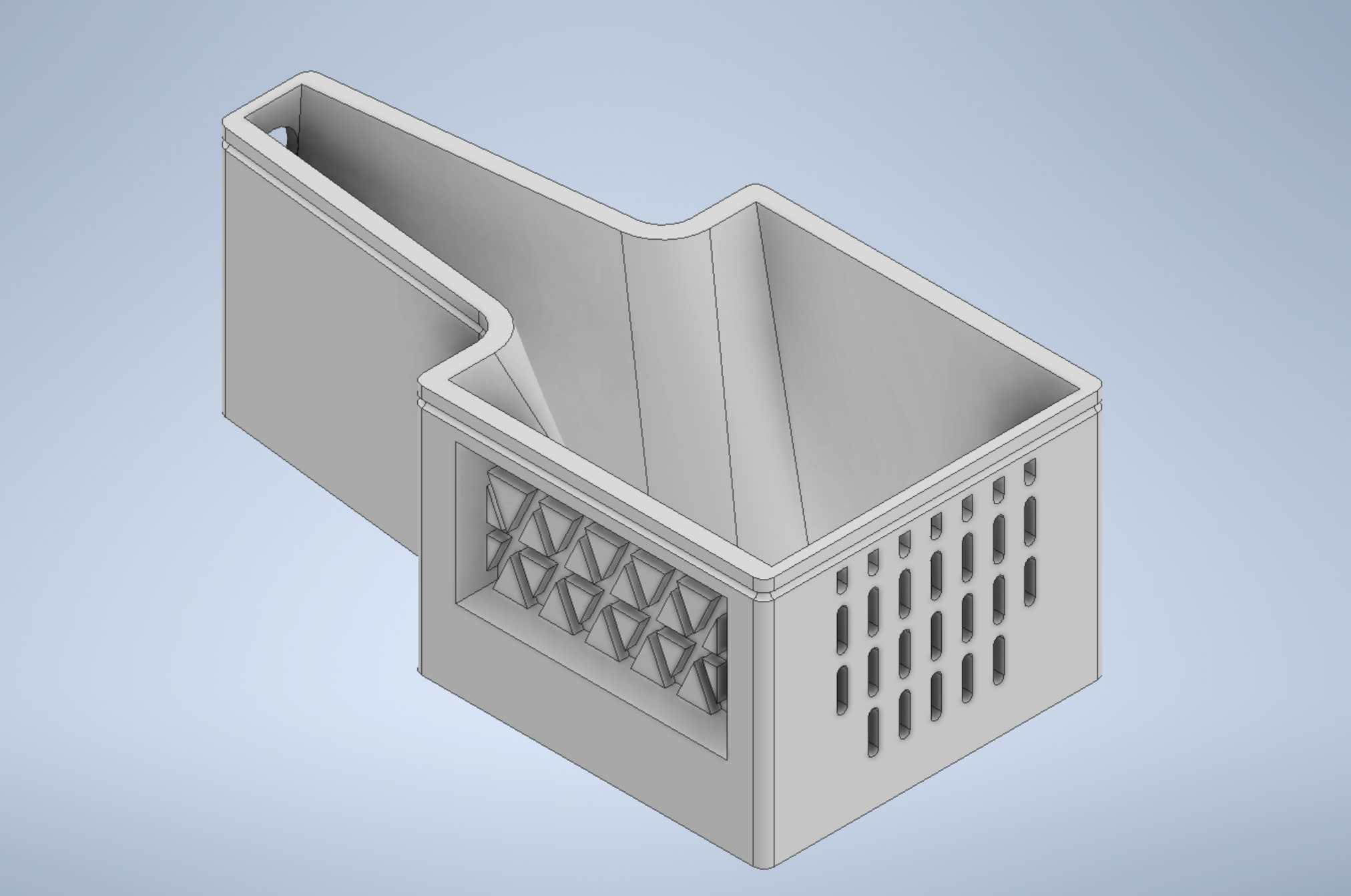
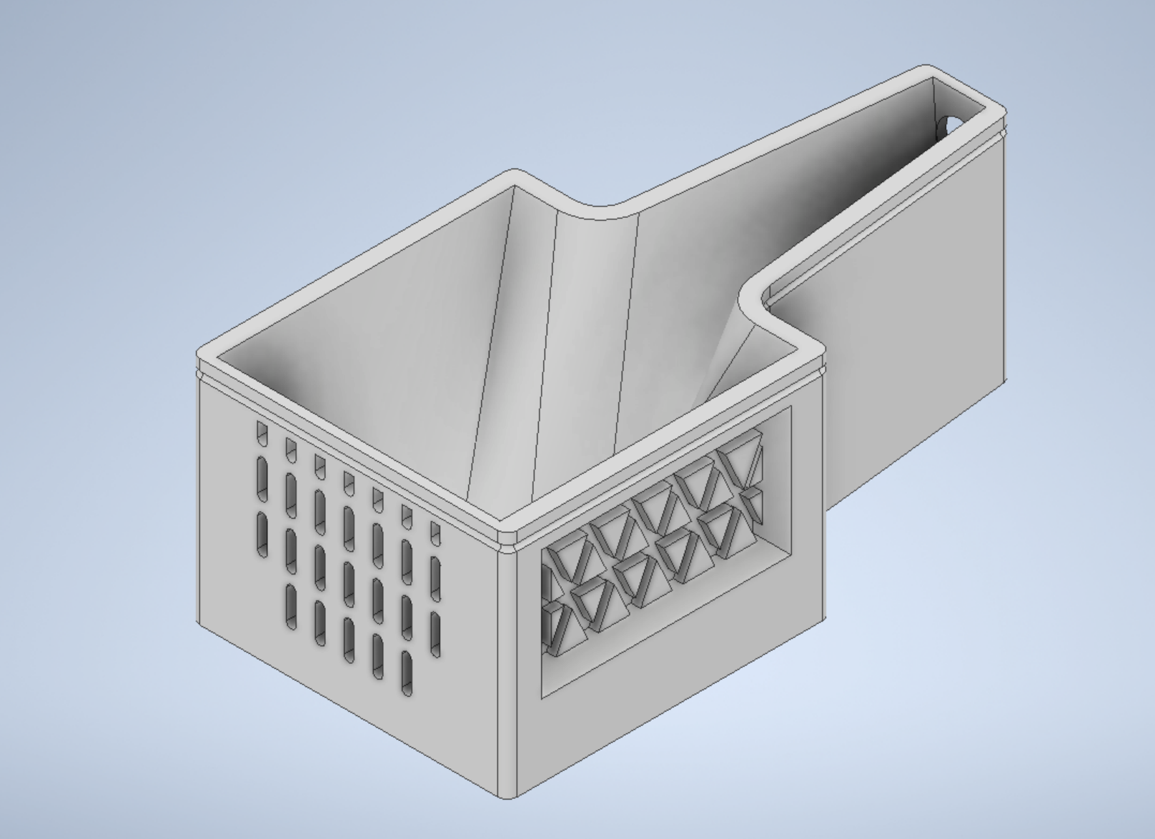
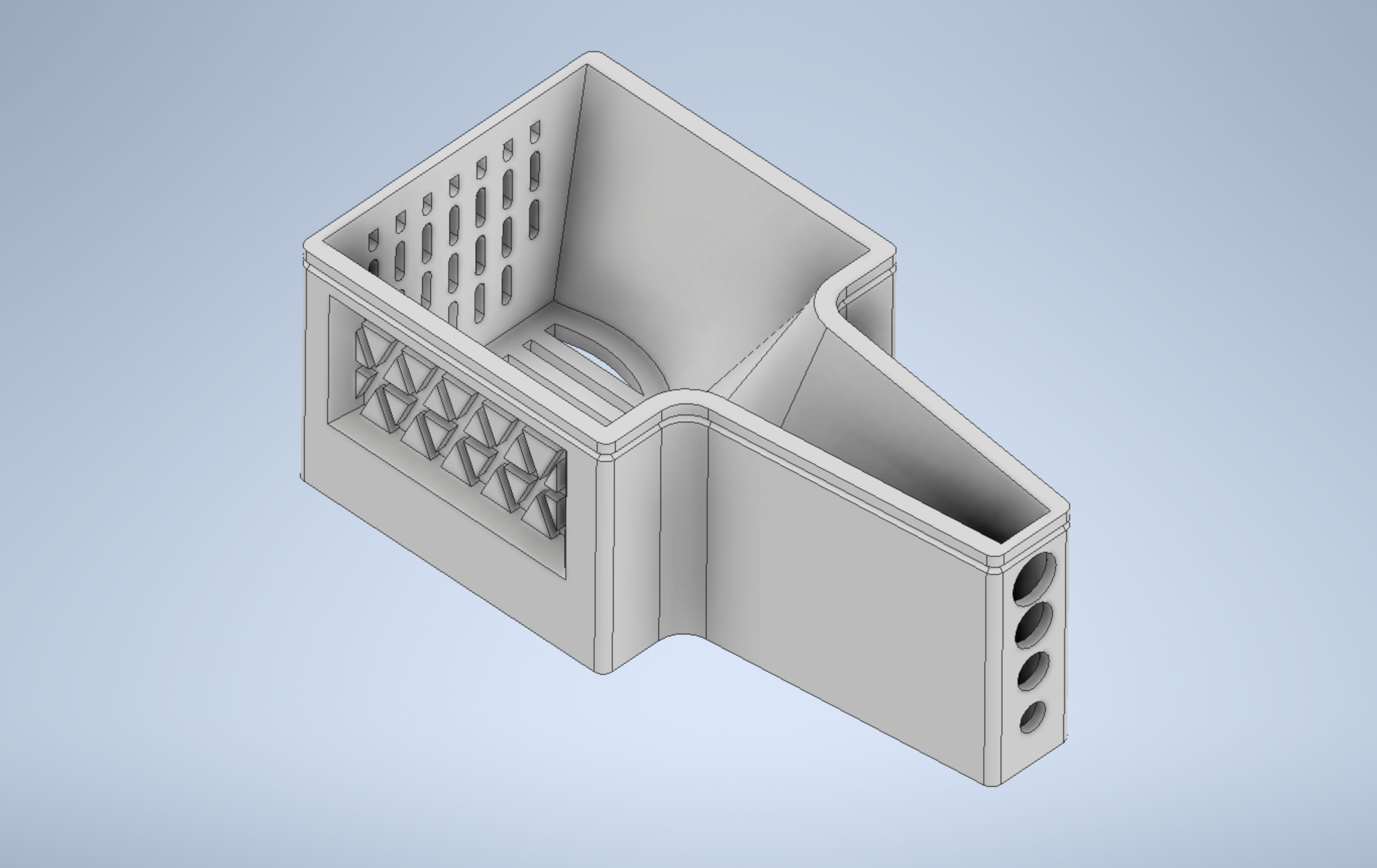
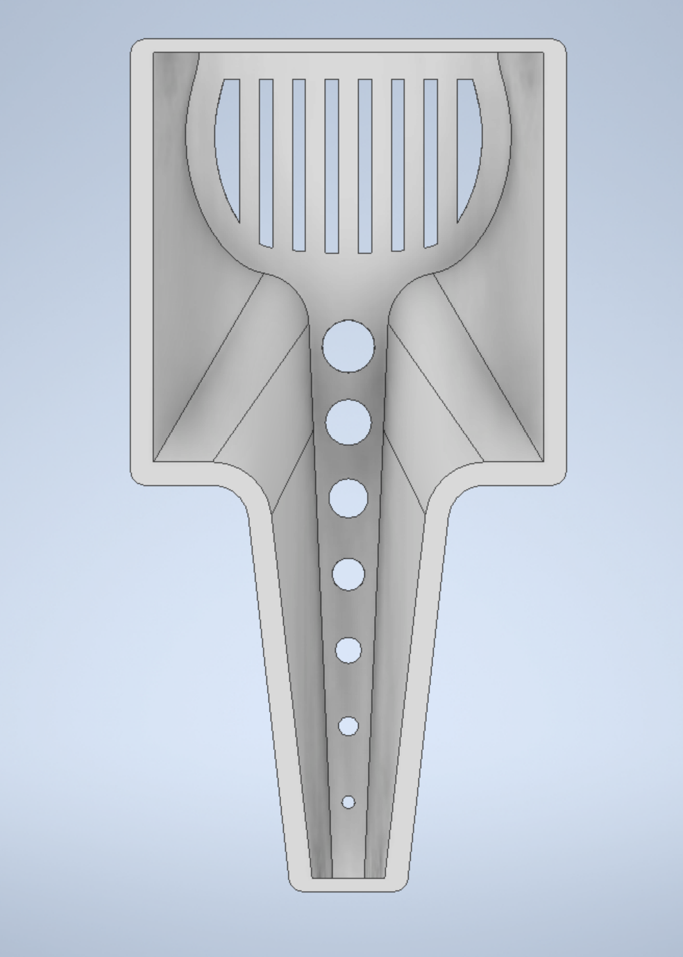
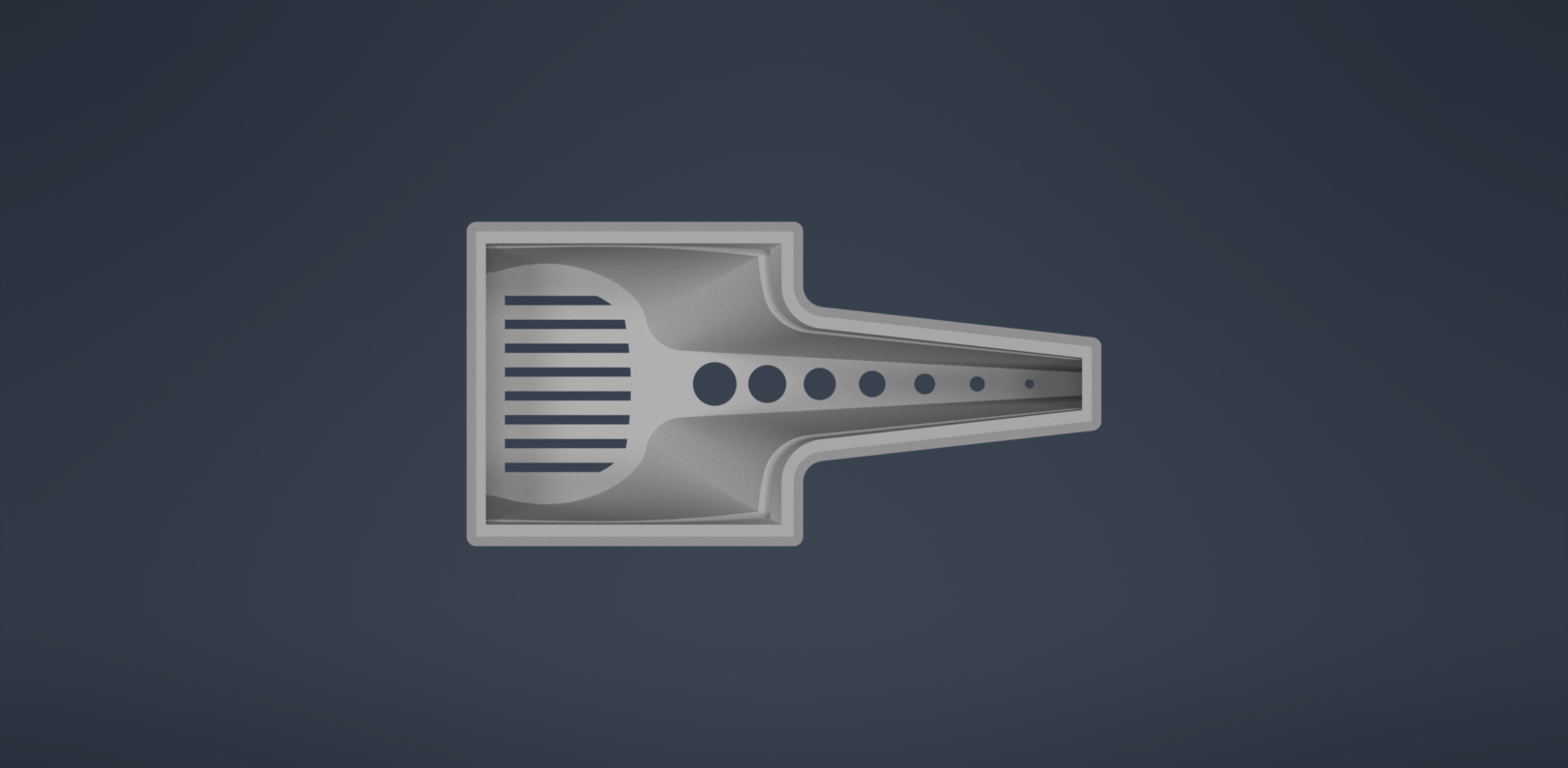
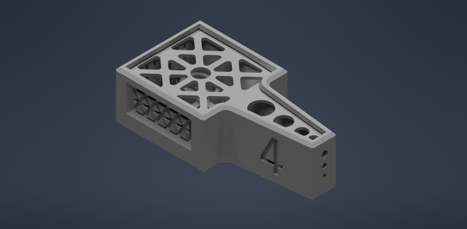
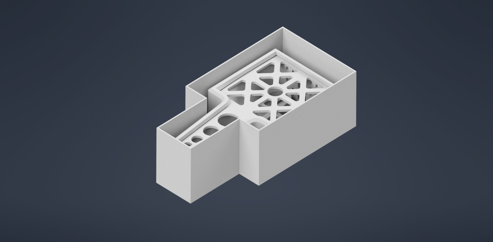
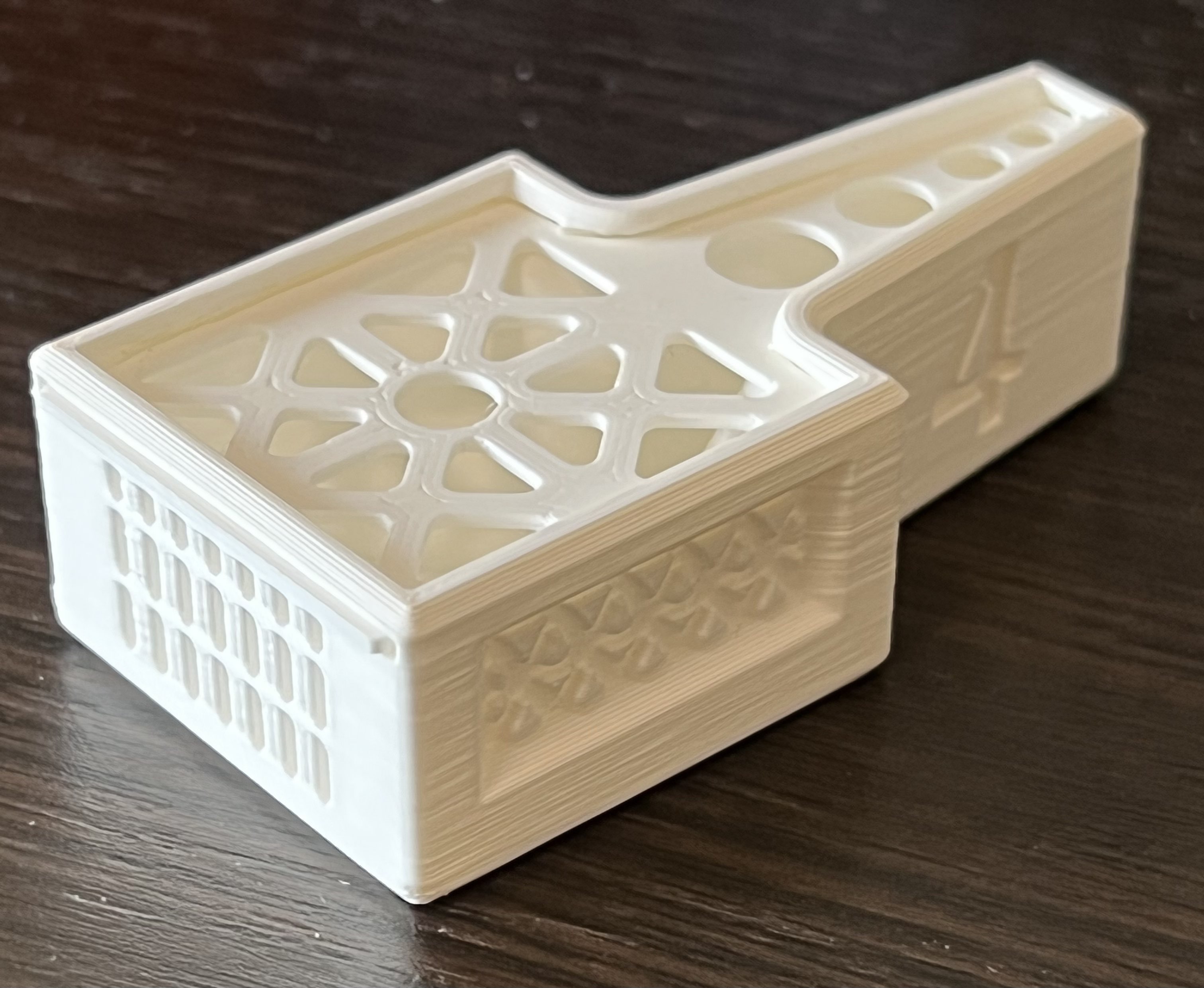
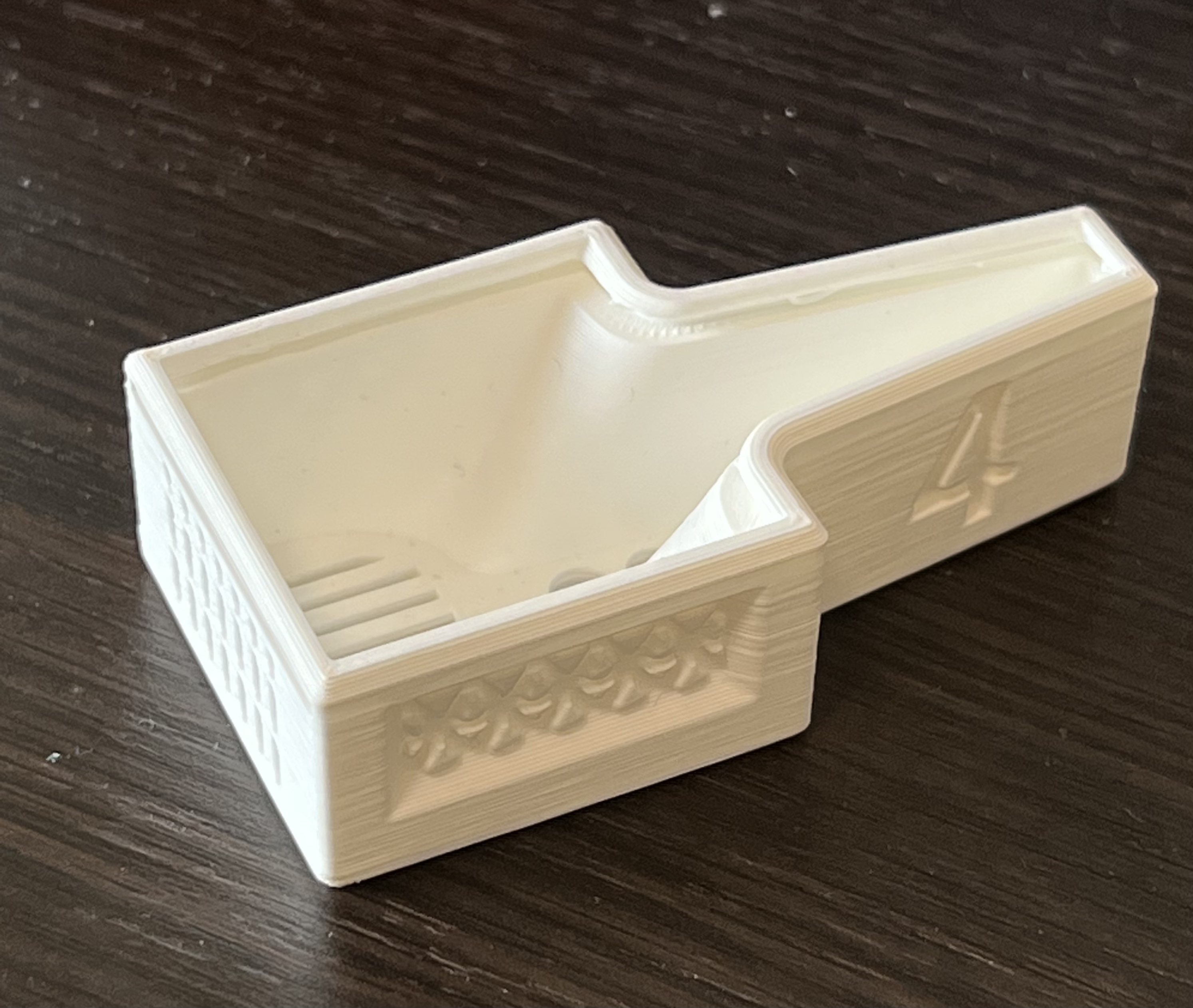
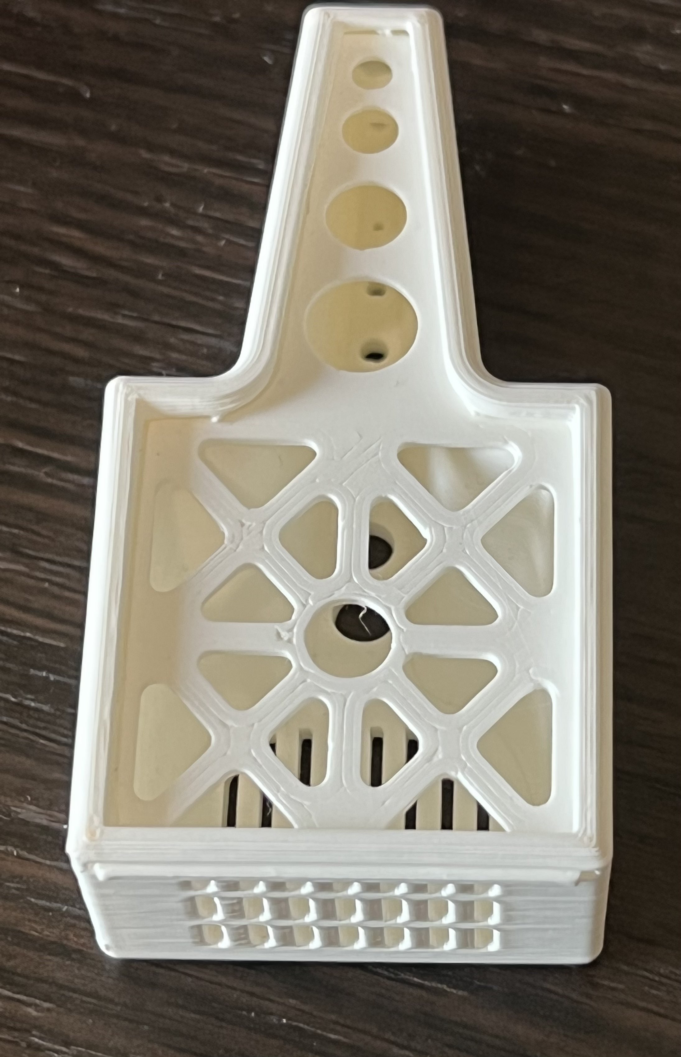
We were challenged as a team to design a system that would transfer surgical tools using a robotic arm to an autoclave bin for sterilization. To accomplish this, we were split into a design subteam and programming subteam. I worked on the design of this system and through the engineering design process created a container that would meet our objectives and constraints. We defined objectives to allow a secure hold of a clamp (the medical tool assigned to us) in place, allow for sterilization, and will be transported by a robotic arm. The design was constrained through the size and shape of our footprint, a mass of under 350g, and maintaining features greater than 2 mm. Our design implements a lofted mould of the clamp that will securely hold the tool as it falls in place laterally and a slide-able lid that would account for any form of displacement—specifically in the event the container was flipped—during transportation. The design conforms to the size and shape of the footprint as a scaled-down version of the geometry allowing for additional space translationally. Furthermore, to facilitate sterilization, lightening holes were created around the container and lid while maintaining structural rigidity by complying with feature constraints and structurally sound patterning.
Prototyping
Generally, when you are introduced to a problem oftentimes there won't be any inherent solution that will come up. Our design process worked quite similarly, as we had to first define our objectives and determine means to acheive these objectives. Having said that we worked on creating a morph chart so that we would have some indication of how we should approach our design.
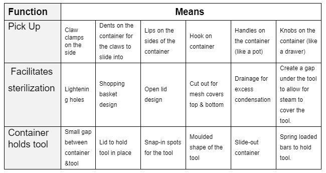
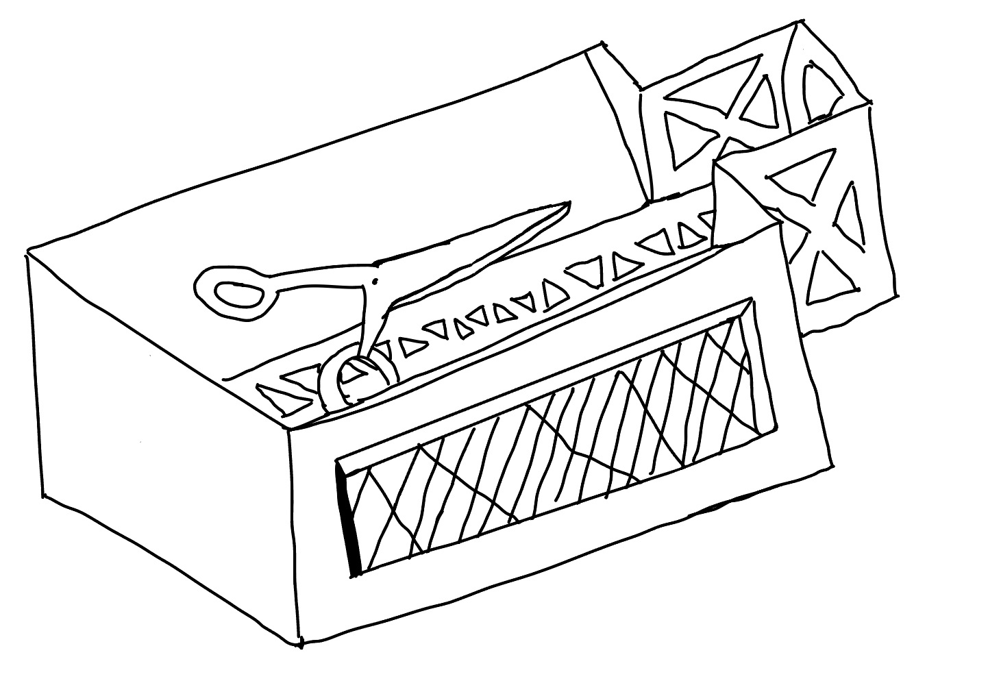
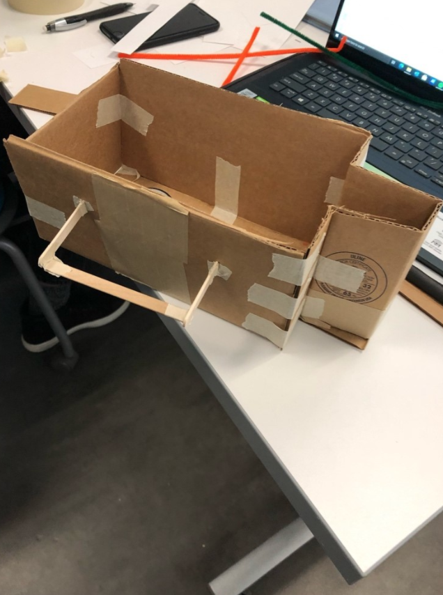
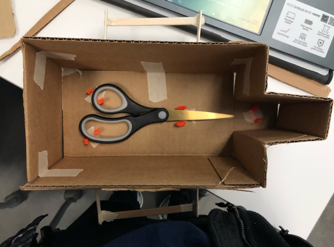
From there were experimented with potential designs with preliminary sketches and prototyped to ensure the design would work from a practical standpoint.
CAD Evolution
From then on, most of the work was done over CAD. This was one of my favourite parts of the project because implementing CAD gives a strong sense of how your design will come to fruition and reveals what parts will be able to work or where the weakness in your design exists.
First CAD Iteration
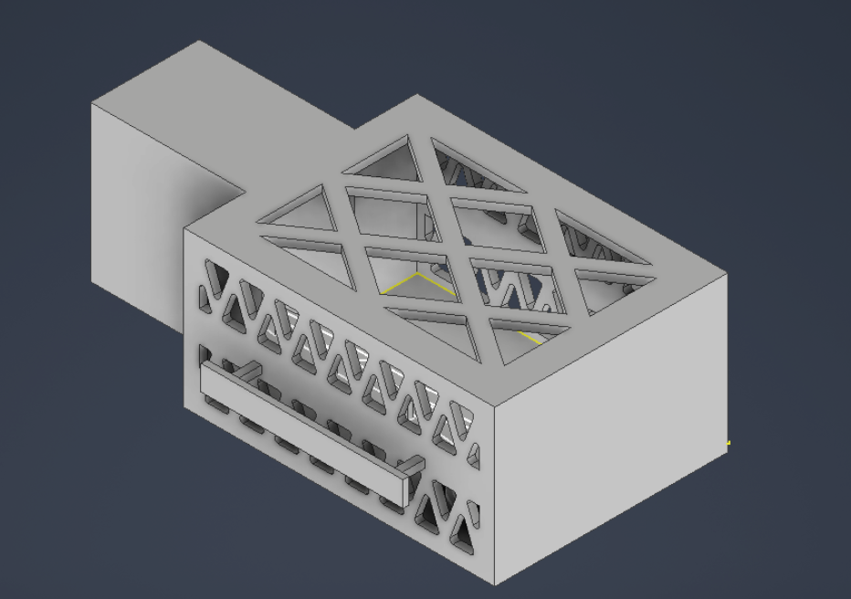
It was pretty clear that the first iteration of my CAD model was not very functional and practical in terms of the problem we were trying to solve. Although, this was a fairly quick and non-technical mock-up of what we wanted the design to be, it helped highlight several issues with our approach. The handle was designed too fragile and weak, we also didn't know if the claw would be able to fit through the handles (also given that it would be difficult to extend it out anymore when we were constrained by our footprint). Knowing that one of the weakest parts of this model was going to be one of our primary objectives, we quickly veto'ed the idea of using handles. The latches also did not make much sense from a practical standpoint because the objective the design is to automate sterilization so that surgeons may focus on monitoring more important things.
Second CAD Iteration
We had to rethink our approach and one of the key highlights and values of the problem. So, we decided that the best way to avoid any non-automated work was by creating a mould that would help funnel the tool to the bottom just by dropping the tool into the container. As for the how it would be picked up, we decided by adding cross hatches to the sides of the container would be sufficient as it would provide friction for the claw to grab. This time, I gave myself more time to design and think about the outcome of the container so the CAD model was much more polished for fabriation. At this point, we were fairly ahead so we waited for design review and considered the modes of failure of our design. Aside from tolerance concerns with 3D-printing, one consideration we had was if the arm were to flip over during transportation which would cause the tool to fall.
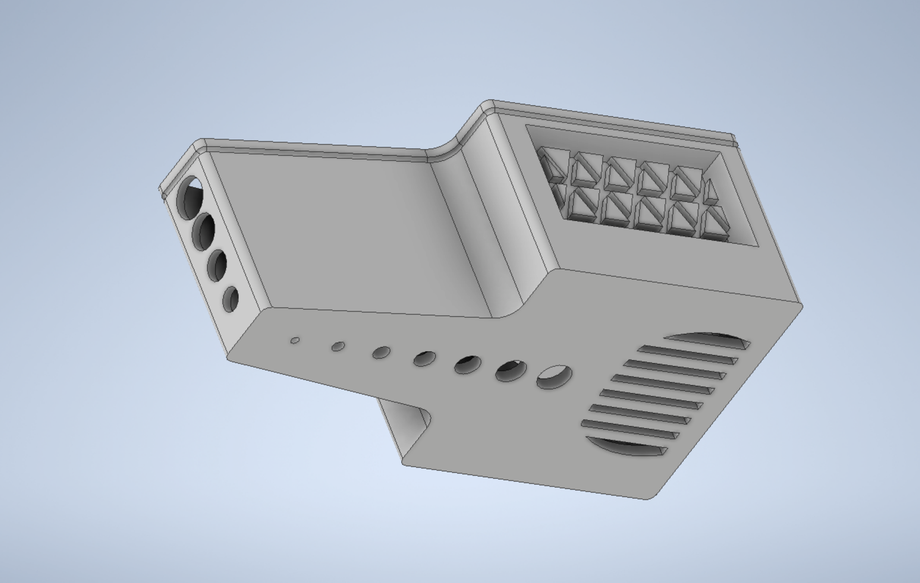
Final Product
After realizing there was a mode of failure in our design, we addressed it by adding a lid to the container that would slide in and out fairly easily without falling out on its own either. That made it so that the tool would be indefinitely secure during transportation. From there, we got the container 3D printed as a mockup of how it turned out.
FRC 2021 Off Season
Due to the nature of COVID, the lockdown limited what our FRC team could do for the off-season. I participated in design training which consisted of creating a drivetrain subassembly for the 2020 season robot. Traditionally, our team generally uses six wheel tank drivetrain which was what I defaulted to.
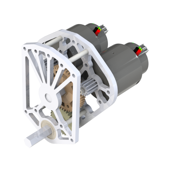
Gearbox
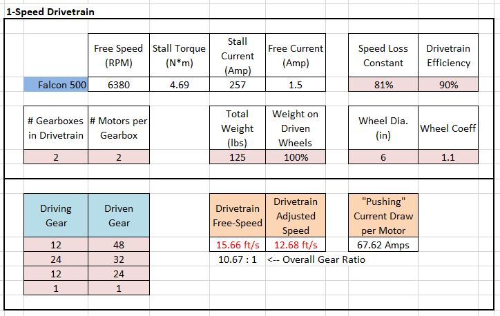
Using a design calculator I determined what my gear ratios should be so that I could design the gearbox.
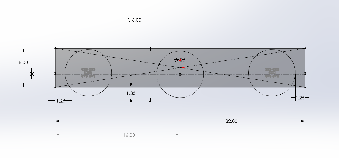
Sideplate
The sideplate is one of the first parts that I worked on for the drivetrain. Generally, this part is easiest to start off with first because you can link other dependencies and relations to it.
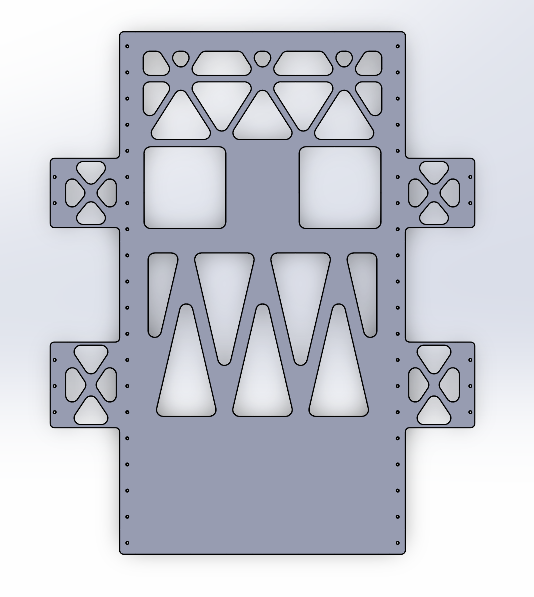
Bellypan
An Unfinished Project
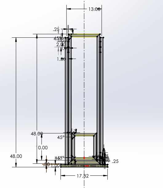
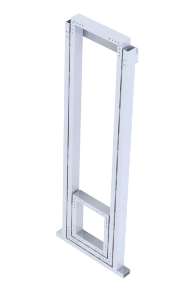
During the off-season, I also worked on creating an elevator subsystem and, although I didn't get to finishing it there were a few important takeaways from this project. The frame of the elevator was made using parametric sketch and multibody parts; meaning the main frame and design of the elevator was made based off a single sketch. The benefits of having a parametric sketch when the dimensions need to be changed is that the parts are reflexive, so changes in one sketch could update the features across the assembly. For this project, I implemented multibody in Solidworks, which in essence, allows me to create parts for assembly from the individual solid bodies of a part.
FRC 1325 - Infinite Recharge
In 2020, I had my first exposure to a real sense of engineering practices outside of what school taught by participating in FRC. I learned about the iterative engineering design process as the team progressed throughout competitiion season.
The Infinite Recharge game involves two alliances of three teams each, with each team controlling a robot and performing specific tasks on a field to score points. The game centers around a futuristic city theme involving two alliances consisting of three teams each competing to perform various tasks, including shooting foam balls known as Power Cells into high and low goals to activate a Shield Generator, manipulating a Control Panel to activate this shield, and returning to the Shield Generator to park or climb at the end of the match. The objective is to energize and activate the shield before the match ends and asteroids strike FIRST City, a futuristic city modeled after Star Wars. [1]
The team split the mechanical design into a set of several subsystems: drivetrain, climber, intake, feeder, panel spinner, and the shooter.
Manufacturing
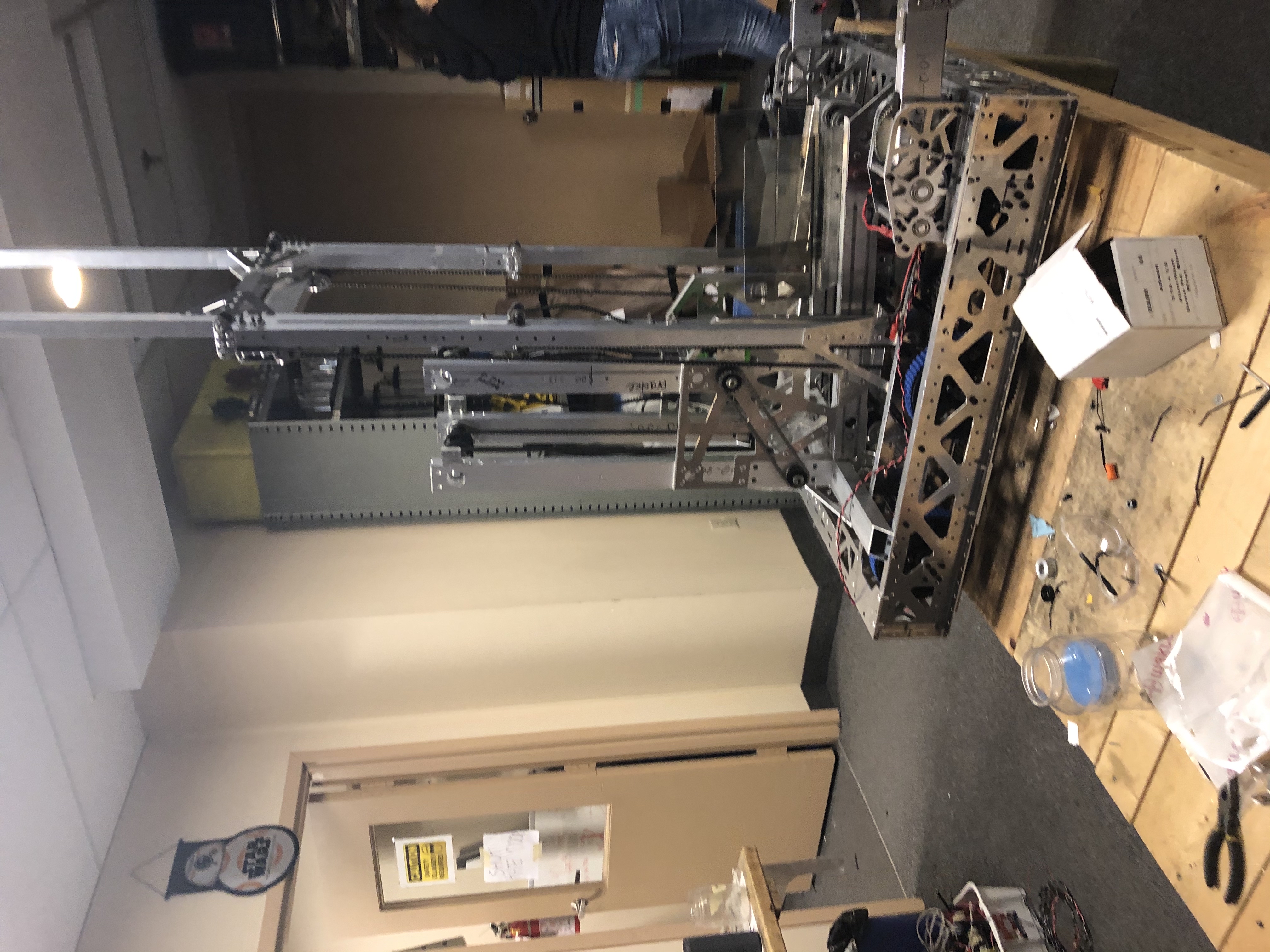
Of all the skillsets that I had acquired over the competition season, I gained the most practical experience during our build season. I manufactured components from the shooter, drivetrain, elevator, intake system, and more. I used tools range from jigsaws, riveting tools, sheet metal benders, drill press, and etc. I manufactured components both for the practice robot and competition robot which helped develop my sense for creating parts from drawings and assembling parts in context to a larger assembly.
Subsystem
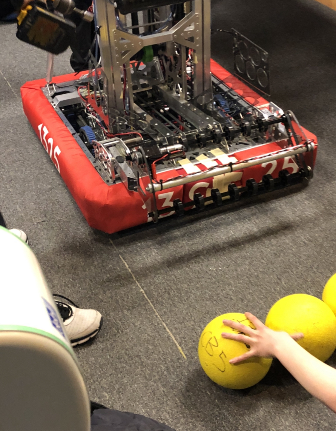
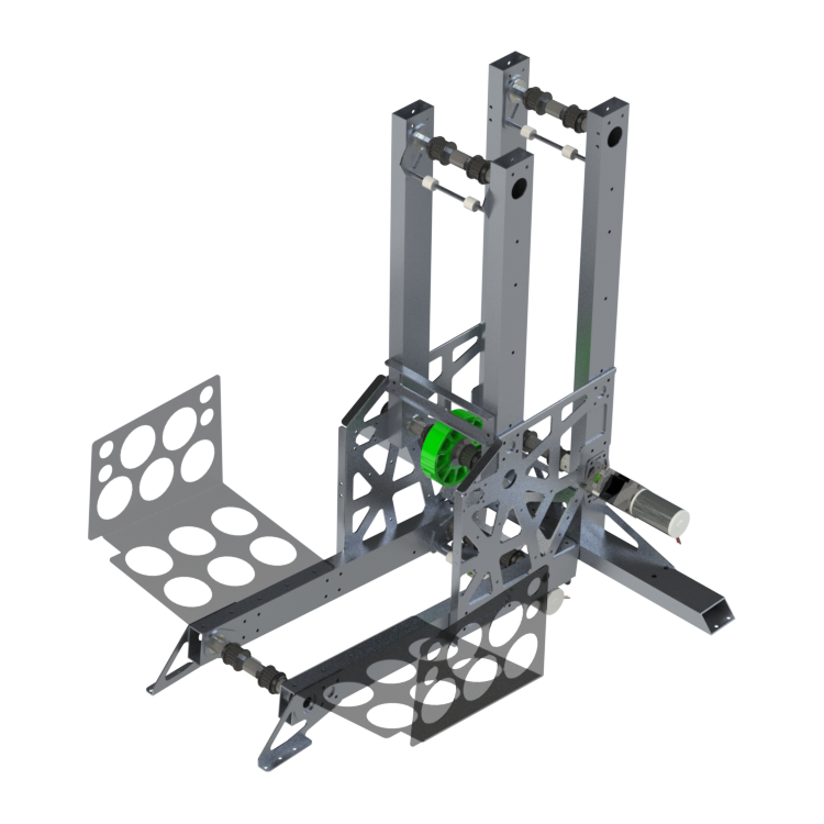
During the design process I was able to work on a few components of the feeder subsystem. The objective of the feeder is to receive the objective (power cells) from the intake and transport it to the shooter element. This subsystem uses timing belt pulleys to pull the ball upwards and since the ball is compliant, additional compression was accounted for in order to transport the ball flawlessly each time.
Mechanical design of turbine blades in renewable wind technology
As a preface, groups were assigned a variety of scenarios that revolved around designing a turbine that would serve as a form of sustainable and feasible production of energy using the wind. From this we needed to be able to analyze the design considerations (both geometrically and material-wise) with high considerations of the objectives of the design given by our scenario. Project 1 implements many new engineering skills and principles, all while relating itself to an engineering scenario. We learned how to apply the engineering design process into a project-based setting as a means of compartmentalizing the problem and ensuring that all possible alternatives are being considered as a solution. The material properties sessions provided a basic yet fundamental understanding of how constraints and variables can be arranged to determine an ideal material. Additionally, we gained experience with using Granta through plotting out the materials by the MPI and using the index (slope of the MPI) to determine an ideal material for the application. The design lab taught and reinforced basic CAD modelling skills using Autodesk Inventor — from essential modelling features to simulating stress analysis on our material for deflection. Project 1 simulated the experiential learning of engineering as forms of interconnected modules that taught different skills over a period of time. We were able to (using the concepts we learned) break down a scenario to provide a feasible real-life solution to the problem. An additional engineering consideration to look towards is the function of the rotor and considering how much potential output of power the turbine could produce.
Problem Statement
The need to become more sustainable becomes more prevalent each day as pollution exacerbates. Sweden will be at the forefront of sustainability and adopting renewable energy as the leading form of energy by 2045. In conjunction with the Swedish Wind Energy Association (SWEA), a machine neededto be designed that wouldtake the kinetic energy of wind to be transferred as a form of electricity. The mechanical system wastobesituated in a new wind farm as a series of machines that would efficiently power multiple cities at a time. Through an environmental analysis, the mechanical system needed to withstand a load of 3000 Pa and a wind speed of 70m/s. To align our goals to the client, we focused on creating a low footprint production—overall minimizing the net carbon emissions of Sweden. Moreover, the mechanism must be reliable and robust—which must withstand external weather factors along with the wind—tomarginalize the chance of failure and achieve relatively infrequent maintenance. Furthermore, to effectively supply energy for various cities, the design must yield high efficiency through an optimized blade length to capture a viable amount of wind.
Inventor Solid Modelling
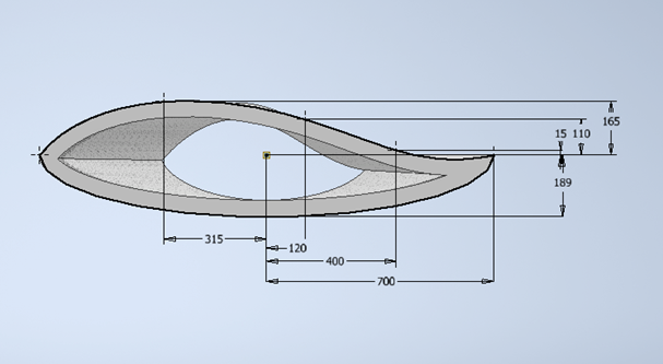
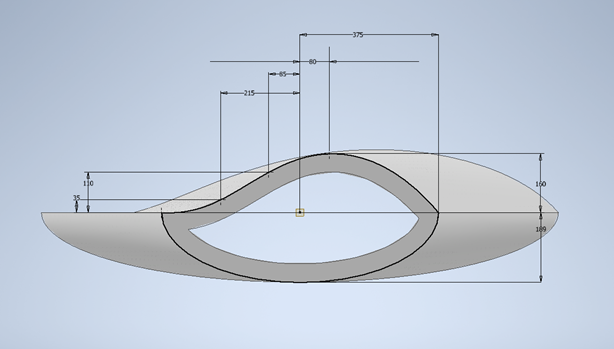
The CAD design of the turbine blade is fairly simple. It is based off two base sketches that are offset 8.5m. Then the sketches are lofted and subsequently shelled.
Granta Analysis
A material analysis was performed based on 4 different objectives. I worked on minimizing production energy based on the specifc strength of the material. The plot compares the energy production relative to the density of the material while taking into account the yield strength. Ideally, a higher yield strength is preferred so that the blade is able to convert the kinetic energy of the wind properly. Subsequently, it would also reduce chance of failure as the blade would deflect less.
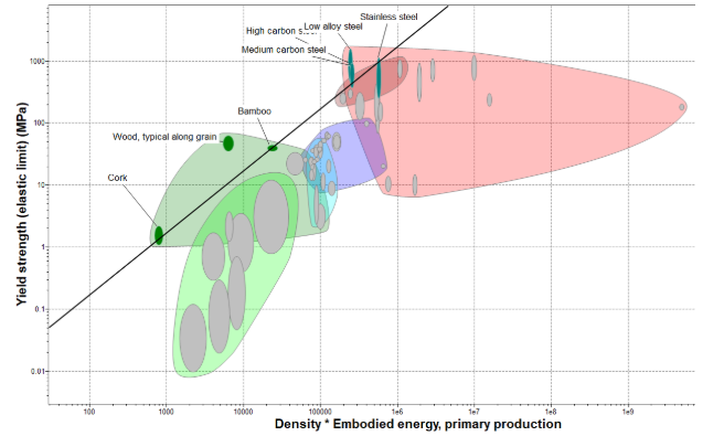
We used a weighted decision matrix to determine that low alloy steel would be the most ideal material to use based on the material analysis and other considerations.
Stress Analysis
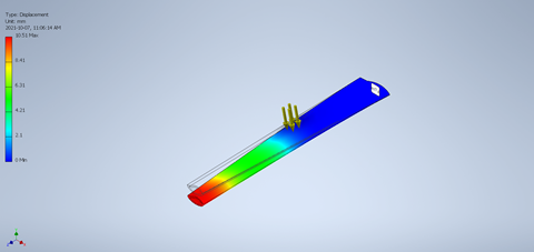
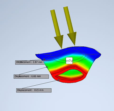
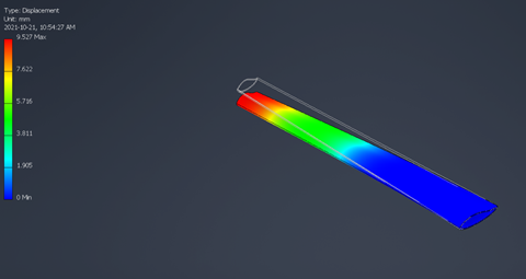
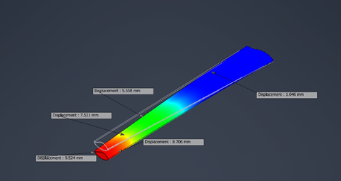
A stress analysis was performed to ensure that the material of the turbine blade fell within the constraints; that falls within a range of deflection displacement. This was done in Inventor by changing the material properties of the turbine blade and using a stress analysis to determine the displacement under 3GPa.
